Computer controlled solid state relay
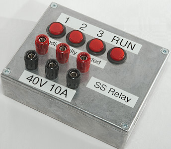
For testing I have made a couple of computer connected relays, all with mechanical relays inside, but I would like to get one with mosfet transistors. My requirements are:
- 2 to 4 MOSFET transistor outputs with power MOSFET's.
- All channels isolated separately.
- Button to toggle outputs manually.
- Leds to show state of outputs.
- Easy computer connections.
- Commands language matching my other relays.

I have not included the buttons and the leds in the above schematic, they are connected directly to any spare Arduino pins. This means it must be something like this with multiple output stages.
Content
Computer controlled solid state relay
Selecting parts
Some ideas
Drawing schematic and PCB
Assembling the unit
Part list
Testing
Software
Manual for the final solid state relay box
Specifications
Button functions
Command format
Mode relay output
Mode PWM
Mode push pull PWM
Mode with pulse output
Mode with multiple pulses output
Mode with pulse on all outputs simultaneous
Mode where outputs turn on in sequence
Mode where outputs are updated from a pattern at regular intervals
Programming
Miscellaneous commands
Repeating output
Control software
Applications
Notes
Selecting parts
First part of the project is selecting some of the key parts, I can always change my selection during the design if something do not fit.
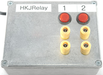
For a box I would try to uses this size and type here, as can be seen I have used for for another relay box.
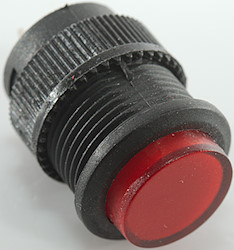
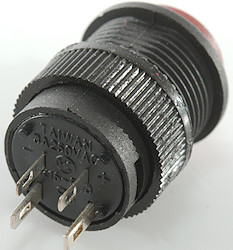
This also makes it obvious to use the same buttons. They are momentary and have a build in led, being round makes it easy for me to mount them in the box. This is perfect for my needs here.

I always use good quality binding posts on my homemade equipment. These are strong and rated for 20A.
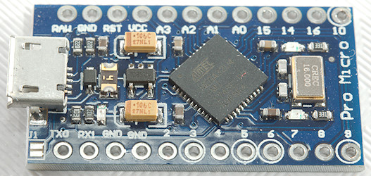
For processor I want a small Arduino with USB, this means either a Nano or Pro Micro. The Pro Micro has a micro USB connector and is the smallest one, because USB is part of the chip. It also has better timers (Two 16 bit and a 10 bit with push pull output and dead time). The mini connector is not used much anymore, this makes the Pro Micro the obvious choice.
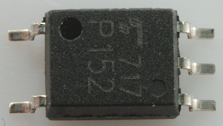
A regular opto coupler is not super fast and not ideal for driving a MOSFET transistor, looking a bit around I found this chip that is opto isolated and fairly fast. Not that fast is important for a relay output or is it (Ideas, see below)?
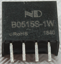
A isolated DC-DC converter is just a 4 pin block, I selected one with 5V input for running from USB power and 15V output to turn any MOSFET fully on. Because the Pro Micro has a series diode and PTC fuse the actual voltage is closer to 4V, not 5V. This is outside the specifications for the converter, it works anyway but with slightly lower output voltage.
Some ideas
With a MOSFET output and fairly fast driver, why not make a few extra functions?
- PWM output on the mosfets, the processor has many PWM channels.
- Adjustable PWM frequency.
- Reading the datasheet for the ATMEGA32U4 shows that it can do push pull and dead time on some PWM channels, this can be useful.
- Pulse output, a command to give a precisely timed pulse.
- Sequence output, i.e. turn the channels on one after another with precise timing.
- Pattern output, update outputs from a byte string at regular intervals.
- Store a couple of commands and activate them with a button, this makes it possible to use the box away from a computer.
First the PWM channels, Timer1 on the Arduino can do 3 PWM outputs each with up to 16 bits, this sounds good. For this to work I need to use pin D9, D10 and D11 on Arduino and I can probably fit 3 channels in the box. There is one problem, the Pro micro do not have a pin D11! I could, of course, solder a wire directly to the chip or probably not, the pins are very small! This means only two outputs and must supplement with Timer3 as another 16 bit PWM channel, one of its 3 PWM channels is available on D5. Then I need a timer interrupt for my button input (This makes a very stable debounce), there I can use Timer4. Timer0 is used by Arduino and I want to use this part of the Arduino library (millis and delay functions).
But what about the push pull output and dead time control, this is only done by timer4 and it can do that on D9 and D10, i.e. the same pins as I already have allocated for output. This can be done by reprogramming the Arduino on the fly to use either Timer1 or Timer4 for PWM.

Here is an example of dead time, there is a short period where both outputs are off when changing between one and the other, this gives the output transistors time to turn completely off.
This makes my final timer allocation:
- Timer0: 8 bit timer, Arduino system
- Timer1: 16 bit timer, PWM output on D9, D10, timer modes on D9 & D10, pattern interrupt
- Timer2: Do not exist on mega32U4
- Timer3: 16 bit timer, PWM output on D5, timer modes on D5, button debounce in push pull PWM
- Timer4: 8 or 10 bit timer, button debounce and push pull PWM on D9 & D10 using 10 bit mode. This timer can be boosted above 16Mhz clock frequency.
With 16 bit timers I get 11 to 16 bit for pwm, depending on frequency, with the 10 bit timer I get 9 to 10 bit. Both will have lower number of bits at the highest frequencies. It is above 7 bits at 100kHz.
Drawing schematic and PCB
Last time I did schematics I used Eagle Cad, but the licensing has changed on it and I have played a bit with KiCad. The first I had to do was adding the Arduino Pro Micro to it:
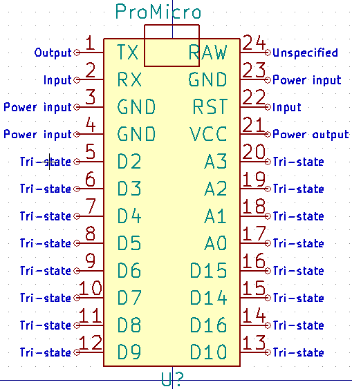
I made it to match the actual ProMicro layout. Grouping the pins according to function is a bit silly here, because most pins has many functions, the only pins there was any idea in placing at other locations was the power pins, but I did not do that.
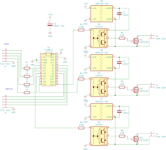
The schematic was easy enough to draw, 3 times the output circuit connected to the PWM output pins from above, LED and buttons can be connected to any other pins on the Arduino. The MOSFET was just a type I had many off and that can handle a lot of current, any type will work. The electrolytic capacitor has to be somewhere between 100uF and 1000uA and more than 5V.
Next question is how to build it? On a breadboard or make a PCB, the opto coupler is SMD and not very breadboard friendly and looking in my box I would soon run out of space. I decided to make a PCB.
KiCad put all the parts in a big heap on the PCB and I had to move them apart and then try to place them logically. When I had placed all parts I printed the layout on paper, checked that the parts fitted, then cut the layout out and put it into my box. In my first placement of components the PCB was too big for 3 outputs in the selected box.
Back to the layout program again and pack the stuff some more. In this phase I did not worry about copper tracks, there is no reason to start on them before the placement is nearly finished. The only consideration to tracks was to place the parts optimally for short tracks, i.e. related parts close together.
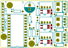
After a couple rounds more with moving stuff around and printing out I got this layout. There is connectors and screw holes (This is important, I do not like gluing stuff in place). With the simple schematic it was easy enough to route it.
Assembling the unit
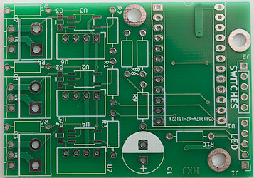
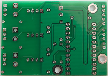
After some time the PCB arrived
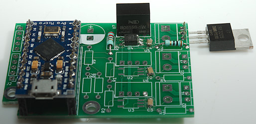
I started by mounting one channel and checking it worked. It did.
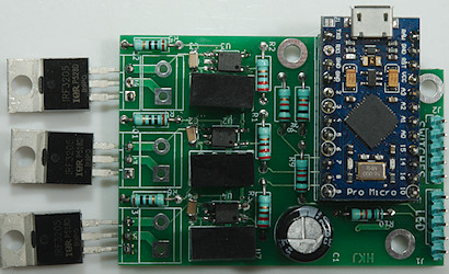
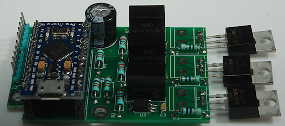
Then I mounted the board fully (I need more training in soldering SMD).
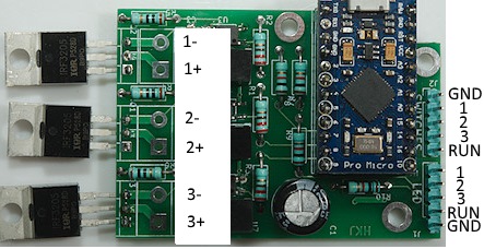
Connections to the PCB.
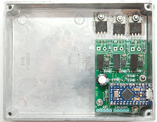
And mounted it in the box I had selected. I used one of the circuit boards as model for drilling the holes and when I had mounted the PCB I drilled through the hole in the MOS transistors. I mounted the MOS transistor with isolation from the box.
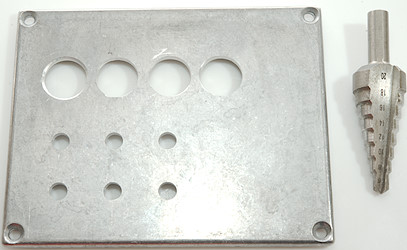
Next up is the front, the larger holes was made with a step drill, this is much easier than using a drill press and mounting the piece properly for drilling.
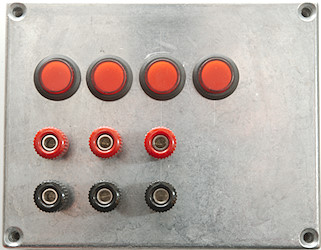
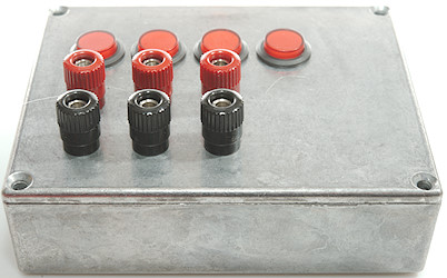
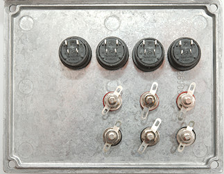
Mounting the binding posts and the buttons was easy enough.
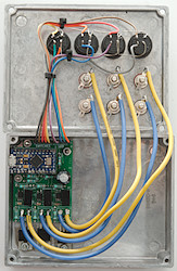
Soldering the wires, now it is ready to test.
Part list
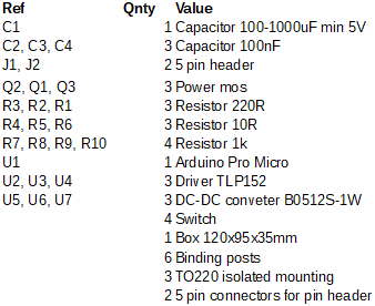
For the MOS transistors I used was IRF3205 55V 110A transistors. They can handle way more current than I need.
The capacitor was a 220uF 16V that I had laying around.
For the wires to the switch and led I used Arduino jumper cables where I cut one end open with side-cutters and stuffed the connector into a 5 pin header, this is much faster than crimping.
Testing
The software was made and tested before I build the box, i.e. I only do a hardware test here.
First test is to check continuity from all MOS transistors to the case, there must not be a connection, I did that test before I mounted the wires.
Drive level for the MOS transistors: 12.39V, 12.35V, 12.39V. This looks fine, anything between 12 and 20V would be good.
The power consumption from USB is 125mA when leds and outputs are off, 167mAh when leds and outputs are on.
I measured the on resistance using a 4 terminal meter, one terminal plugged into the binding post and the other terminal connected to the side of the binding post. The result was around 25mOhm. I wonder how it is distributed (All values in mOhm): red binding post (Top to bottom): 0.1, yellow wire: 3.3, PCB to MOS pin: 2.2, MOS pin to MOS pin: 13.3, MOS pin to PCB: 1.9, blue wire: 2.9, black binding post (Top to bottom): 0.1. This was measured on channel 1 using 1A current through the circuit. There is not anything that looks especially bad. The MOS was rated as 8mOhm and is 13.3mOhm for a Ebay version this is more or less as expected.
Next I use PWM to see how fast the opto-couplers works.
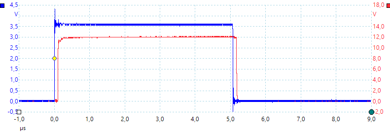
Blue is Arduino out and red is opto coupler out, it looks like 0.1us delay. This is about 1% when using 100kHz PWM.
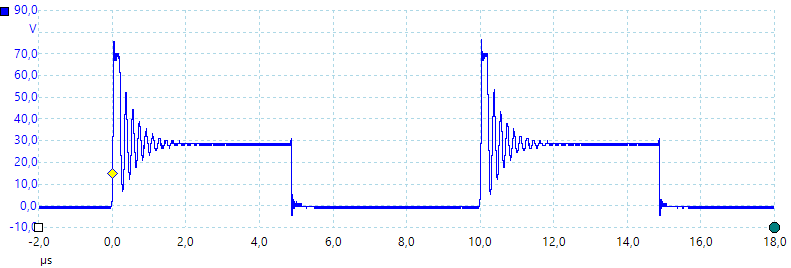
Testing output with 100kHz PWM through a 10ohm resistor, supply is 30V. There are some nasty spikes, could that be due to the wire wound resistor?
The MOS transistor can handle this type of spikes to a certain extend, it is avalanche current and energy in the data sheet. Driving a real inductor in a relay, transformer or motor may require a diode across the inductor.
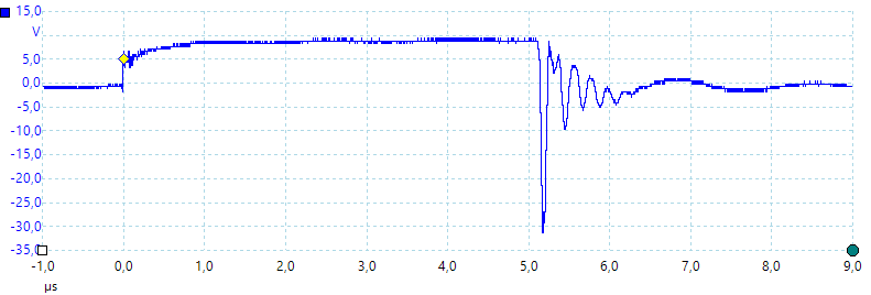
Checking the resistor this time with 10 volt, each time the MOS disconnects (Voltage is supposed to drop to zero) there is a large spike from it.
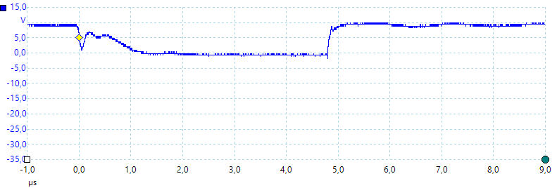
A 100ohm film resistor do not have any spikes, but voltage drops slowly (It takes 1us). This is due to the lower current.
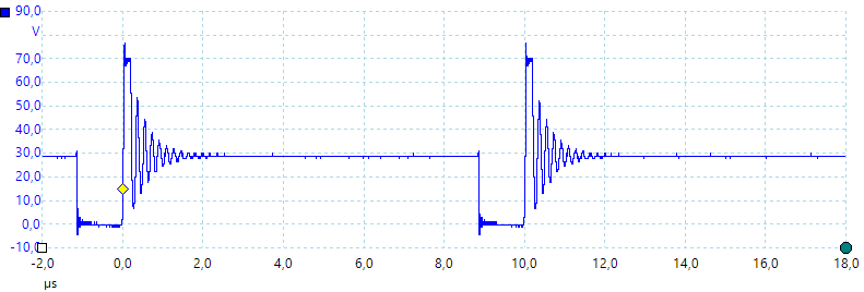
Lets do one more with the first resistor, this time with 10% duty cycle at 100kHz, i.e. a 1us pulse, the pulse looks to be around 1us
And also the other way around, i.e. 90% duty cycle, this means 1us off time. Both looks good.
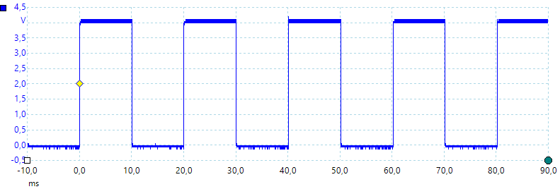
I used my test pin to check how fast the leds update and it is only every 10ms, that is rather slow (I removed the code after the test).
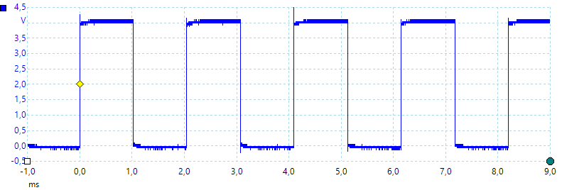
During a "WAIT" command it is every 1ms. A study showed that "if (!Serial) return" takes 10ms, I could remove it without any bad effect.
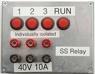
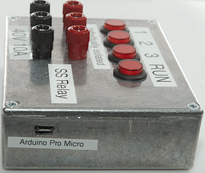
Time to close the box and label it. I selected a 10A rating due to the power loss, this is about 2.5W for each channel. It can handle much more in peak current.
Software
The software is a very important part of this project and it requires detailed control with some aspect of the Arduino Pro Micro. For this reason I use direct register access, this means the software cannot be moved to another Arduino processor without a lot of rewriting. That would be necessary anyway because some of the functions I use are specific to this ATmega processor and do not exist on other ATmega processors.
To handle a very wide time range I uses the build in timers for fast pulses and software timing for slower pulses. All internal values are stored in integer or long, they are faster to calculated on than float and a "unsigned long" can handle up to 10 hours with 10usec resolution, this is enough for me. The software has two strategies for timing, when possible use the build in timers, when the timing is too slow, switch to software timers in a "slow" processing routine.
The software has the usual Arduino setup and loop routines, the loop calls the command processor and the slow handling routines.
There is the following output types support:
- Relays, the basic digital on/off output commands.
- Pulse, a single pulse on one output at a time.
- Pulses, a specific number of pulses, only works on output 1
- Sequence, turn the 3 outputs on in sequence.
- PulseAll, turn all 3 outputs on, then turn each one off after a specified time.
- Pattern, write a new pattern to the output at regular intervales, this uses a interrupt. This updates all outputs.
- Push pull drive, PWM with push pull drive and dead time, this uses a combination of output 1 & 2.
- PWM, regular PWM with separate control for each output, this works on all 3 outputs.
For each of the above there is one or more routines:
- set..., configure the timers and other setup.
- setSlow..., configure software mode.
- updateSlow..., update software mode.
Each command has a "cmd..." routine, it will parse the parameters and if the commands activates some output call the "set..." or "setSlow..." routine. Some commands will only call the "set..." if the actual mode is active (Like PWMFREQ, it only calls setPWM if PWM is active).
cmdWait is the only blocking command, for this reason it needs to call some background routines and looks for key pressed (They will abort the wait).
cmdRun is blocking while the commands are processed, but it will only take a short time, then it returns to the main loop. Even if there is a RUN command inside the list of commands it will return to the main loop, but then resume if there is no waiting commands. This makes it possible to make a repeating program.
All command with "cmd...Q" is a question command and must return an answer on the supplied stream.
Manual for the final solid state relay box
Specifications
- Can turn on/off any of the 3 outputs from a command or from buttons on the box.
- Can generate PWM with a frequency from 1Hz to 100kHz on up to 3 channels
- Can generate push pull PWM with dead time on one channel using output 1 and 2.
- PWM frequency can be specified either as frequency or period time.
- PWM duty cycle can be specified either as percent or as high time.
- PWM has a resolution up to 0.1%
- Frequency can be specified with on decimal
- PWM duty cycle can be specified with on decimal
- Time is specified default in milliseconds with two decimals, some other time units can be selected by a letter after the value.
- Timed commands works up to 10 hours
- Time specifications below 4 seconds uses hardware timers with available resolution down to 10us
- Time specifications above 4 seconds uses software timing with 10ms resolution.
- Output 1 & 2 are synchronized, output 3 can be up to 1us late.
- Can sequence the outputs, either with pulse length or when they turn on.
- Commands can be stored in the device and activated with a button for off-line usage.
- Outputs can handle 10A continuous and much more in peak.
- Can deliver pulses below 1us in PWM mode.
Button functions
- In relay mode button 1 to 3 is used to toggle output
- In PWM modes button 1 to 3 will select 0% duty cycle, next press will switch all channels to relay mode with output off.
- In all other modes button 1 to 3 will change to relay mode with output off, i.e. next press will turn output on.
- Button 4 will run a stored program.
- The stored program can be either one program or four programs where one has to be selected with another button press after pressing button 4.
- When a program is running any button press will cancel the program and not do any other function on first press.
Command format
The box can only use one mode at a time.
A line can contains one or more command with ; between.
Commands are case insensitive, i.e. pwm, PWM, pWm is exactly the same command.
Commands are not blocking, but parsed and then executed in the background (WAIT is blocking).
Any command ending with ? is a query and will return some data.
Unknown commands and wrong parameters are ignore, there will be no error messages.
Mode relay output
This was the main mode for the unit, it can turn on/off each of the 3 MOSFET transistors, one at a time or with a bitmask, it is made to match my other relay boxes. This gives the following list of commands.
- RELAYON no
- RELAYOFF no
- RELAY? no
- RELAYS bitmask
- RELAYS?
No is output can be 1, 2 or 3
bitmask is a OR of bit 0, 1 and 2, i.e. 0-7 and will turn the corresponding relays on and off (Note: PATTERN uses the same values).
When using "RELAYS" outputs will turn on/off at the same time.
Mode PWM
The regular PWM mode can use all 3 MOSFET outputs with separate duty cycle, but all must use same frequency (I could have implemented a separate frequency selection for output 3). The commands are:
- PWM no duty_cycle
- PWMW no ms
- PWMFREQ frequency
- PWMPERIOD ms
- SERVO no %
- PWM?
- PWMFREQ?
No is output can be 1, 2 or 3
duty_cycle is duty cycle with one decimal place, i.e. 10.1 is a valid value. When above 16kHz the decimals will be rounded a bit.
ms milliseconds, it is possible to specify duty cycle as ms high time or frequency as ms period time, two decimal place is supported.
frequency is PWM frequency, from 1Hz up to 100000Hz is supported, no decimal place are accepted.
% percent of servo range, this requires a pull-up resistor on the output to drive a servo.

Commands for above curve:
PWMPERIOD 8 Set period of PWM to 8ms, this is the same as "PWMFREQ 125"
PWM 1 30 Output 1 is on 30% of the time
PWM 2 50 Output 2 is on 50% of the time
PWMW 3 7 Output 3 is on 7ms of the 8ms cycle time.
PWM? This command returns: "30.0%,50.0%,7.0ms"
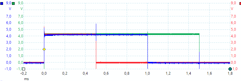
Commands for above curve:
SERVO 1 50 Neutral position for a servo
SERVO 2 0 Minimum position for a servo
SERVO 3 100 Full position for a servo
The SERVO command will set the PWMPERIOD to 20ms and puls width (PWMW) between 0.5ms and 1.5ms for a 0 to 100 range.
Mode push pull PWM
This PWM mode only uses output 1 and 2, the 3 output cannot be used. There is support for dead time and push pull output. The timer is only 10 bit, but input frequency can be adjusted in x2 steps, meaning that there always is at least 9 bit resolution.
Some of the commands are the same as for regular PWM.
- PPPWM duty_cycle
- PPPWMW ms
- PWMFREQ frequency
- PWMPERIOD ms
- PWM?
- PWMFREQ?
- DEADTIME us
duty_cycle is duty cycle with one decimal place, i.e. 10.1 is a valid value. When above 20kHz the decimals will be rounded a bit.
ms milliseconds, it is possible to specify duty cycle as ms high time or frequency as ms period time, two decimal place is supported.
frequency is PWM frequency, from 1Hz up to 100000Hz is supported, no decimal place are accepted.
us deadtime in micro seconds, this value is saved in EEPROM and will be used again at next power on.

Commands for above curve:
PWMFREQ 10000 Use 10kHz PWM frequency
PPPWM 50 With 50% duty cycle
DEADTIME 2 And 2usec dead time
Mode with pulse output
Pulse one of the 3 outputs on for a specific time, this is controlled by a timer and will be stable and precise. Only one output can be pulsed at a time, but when the pulse is finished another pulse on any output is possible. The command do not block, this means another command may abort this command if received before the pulse is finished.
No is output can be 1, 2 or 3
ms milliseconds on time for output, it is possible to use two decimal places.

Commands for above curve:
PULSE 1 4.5 Perform a 4.5ms pulse on output 1
Mode with multiple pulses output
Pulse output 1 with a specified number of pulses. The on time, off time and number of pulses can be specified.
The command do not block, this means another command may abort this command if received before the pulses is finished.
- PULSES onTime offTime pulses
onTime is on time in ms
offTime is off time in ms
pulses is number of pulses to output, specifying 0 means do not mean zero pulses will give a nearly endless stream (>4 billion pulses).

Commands for above curve:
PULSES 10u 20u 4 Output 4 pulses, each 10us wide with 20us between
Mode with pulse on all outputs simultaneous
Turn all outputs on at the same time and turn each output off when that time is expired.
- PULSEALL ms1 ms2
- PULSEALL ms1 ms2 ms3
ms milliseconds on time for output, it is possible to use two decimal places.
Output 1 and 2 shares a timer and resolution will be based on the longest selected interval.

Commands for above curve:
PULSEALL 1 4 7 Pulse output 1 for 1ms, output 2 for 4ms and output 3 for 7ms
Mode where outputs turn on in sequence
This is basically the same as PULSEALL, here the output just stays off until the time is expired, then they turn on. Usual one output will have a 0 time to signal start of sequence.
- SEQ ms1 ms2
- SEQ ms1 ms2 ms3
ms milliseconds on time for output, it is possible to use two decimal places.
Output 1 and 2 shares a timer and resolution will be based on the longest selected interval.

Commands for above curve:
SEQ 0 3.5 7 Turn on output 1 now, output 2 after 3.5ms and output 3 after 7 ms
Before repeating this a OFF command can be used to reset the outputs.
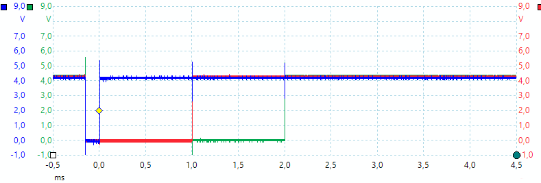
Commands for above curve:
SEQ 0 1 2 Used after another SEQ command
If the OFF command is not used between SEQ command there will only be about 0.15ms with all outputs off before the sequence start, this is the time it takes to reset and prepare the timers.
Mode where outputs are updated from a pattern at regular intervals
This mode uses interrupt, not timers, to control the output, this means there is some jitter (Some us). This command is in multiple versions, the basic one is PATTERN ms sequence, adding REP before it will make the pattern repeat, using it without parameters will reuse the last ms and pattern
- PATTERN
- PATTERN ms
- PATTERN ms sequence
- REPPATTERN
- REPPATTERN ms
- REPPATTERN ms sequence
- PATTERN?
ms milliseconds, outputs are updated at this interval, it can be specified with two decimal places. Using rates below 0.1 is not very stable, due to other interrupts.
sequence A list with up to 64 digits (01234567), the bits from next digit are written to the outputs each ms interval. 0=all off, 1=Relay 1 on, 2=Relay 2 on, 3=Relay 1+2 on.

Commands for above curve:
PATTERN 1 10204070 Update each ms, start with 1 output, then second and 3, final turn all outputs on, there is a ms with all output off between each.
PATTERN? Answers: "1.0,10204070"
Programming
The box can be used offline, it is possible to store a sequence of commands and run them with the 4 button.
- PROGRAM command_list
- PROGRAMADD command_list
- PA command_list
- PROGRAM?
- RUN
- WAIT ms
- SELECTPGM
- PGM1
- PGM2
- PGM3
command_list is a list of commands, the ; delimiter cannot be used, instead use |.
ms milliseconds to wait before executing next command, this must be used after the PULSE, PULSEALL, SEQ, PATTERN commands or they will be aborted when next command is executed. Maximum are 100000 or 100 seconds. Using a button will terminate the wait.
PROGRAM clears the list and then adds its command_list to it.
PROGRAMADD and PA is the same command and will add its command_list to the stored commands.
RUN will start the program, pressing button 4 will also start the program. Including RUN in the program will make it loop (This do not work together with SELECT)
WAIT waits a specified number of ms before executing the next command, this is required to avoid next command aborting previous command.
SELECTPGM will flash all leds, pressing 1 will continue at PGM1, pressing 2 at PGM2, pressing 3 at PGM3, pressing RUN will continue from present position, i.e. next command after SELECTPGM.
PGM1, PGM2, PGM3: Labels and stop, they must be placed after a SELECTPGM. The only time a program will run past a PGMx is when searching for one at all other times it is end of program.
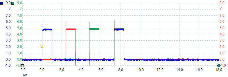
Commands for above curve:
PROGRAM OFF|PULSE 1 1|WAIT 2|PULSE 2 1|WAIT 2|PULSE 3 1|WAIT 2|PULSEALL 1 1 1 Stores this as a program
RUN Run the program, the delay between each command is longer than the WAIT because Arduino needs time to interpret and configure each command.
PROGRAM? Returns: "69,OFF;PULSE 1 1;WAIT 2;PULSE 2 1;WAIT 2;PULSE 3 1;WAIT 2;PULSEALL 1 1 1", the 69 means 69 characters is used, there is space for 500.
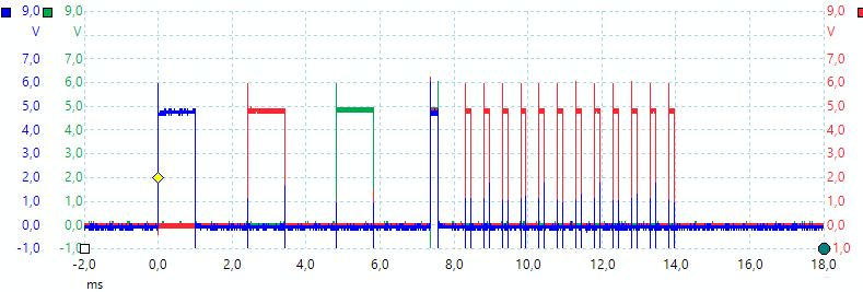
To get the above curve I added the following commands to the above:
PA PWMFREQ 2000|PWM 2 30|WAIT 6|off Add some commands to the program
RUN Run it
PROGRAM? Returns: "102,OFF;PULSE 1 1;WAIT 2;PULSE 2 1;WAIT 2;PULSE 3 1;WAIT 2;PULSEALL 1 1 1;PWMFREQ 2000;PWM 2 30;WAIT 6;OFF"
Because there is no WAIT between PULSEALL and PWM the PULSEALL command is aborted early.

Here is an example on using SELECTPGM and PGMx, when RUN is pressed all all outputs will be turned off, then all leds will flash.
Pressing 1 will pulse output 1 for 1 second, pressing 2 will pulse output 2 seconds, pressing 3 pulse output for 3 seconds and RUN will pulse output for 10 seconds.
It is possible to use any sequence of commands for each button.
Miscellaneous commands
There is a few command more.
- BUTTONS?
- OFF
- *IDN?
- *ESR?
- FREEMEM?
- RESOLUTION?
The BUTTONS? is mostly for testing, the OFF is a shorthand way of turning all outputs off (Same is RELAYS 0). The *IDN? will return a identification string and the *ESR? is basically a dummy command that can be used to get a response when a command line is processed. FREEMEM? shows how much RAM memory is free in the Arduino.
RESOLUTION? will return the actual timer value used, this gives an idea about the resolution used for the command.
Repeating output
There are a couple of ways to repeat a output depending on command and then there is the general way to repeat anything.
The general way is storing the commands as a PROGRAM, then they can be executed again with RUN or a button press. Adding RUN to the stored commands will automatic repeat the list of command until a new command is issue or a button is pressed.
The PATTERN command has a build in repeat function, it can be used without parameters to repeat the last command, it is also possible to use a REPPATTERN to continuous repeat the data.
RELAY and PWM commands will maintain their output until another command is given or a button is pressed.
Control software
The relay can be controlled from any terminal program like "Putty", "Realterm" and "Yat", it can also be controlled from the included program or from your own program.
The included program is in Java and will work on both windows and Linux if Java is installed and it has access rights enough (This is a Linux issue for serial ports).
The software I have written is a very simple program that just sends the command and displays any response, it do not do anything else. The input fields are copied directly to the box with the command added in front of the text.
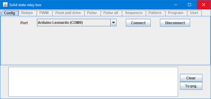
When started it shows this page, the software will automatic select a port called something with Leonardo (Some ProMicro uses that). If not use the combobox to select the correct port.
Press "Connect" to start.
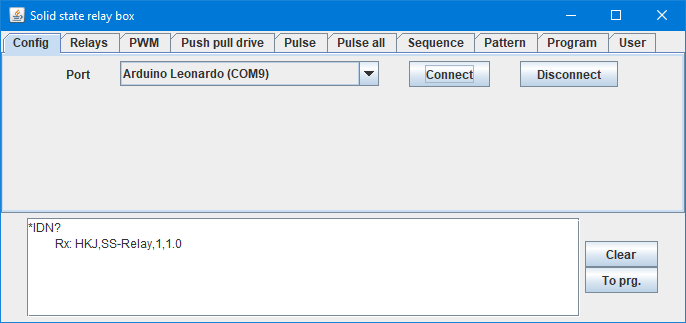
When connected it will enable all pages and use a "*IDN?" command, the answer will show what it is connected to and the software version.
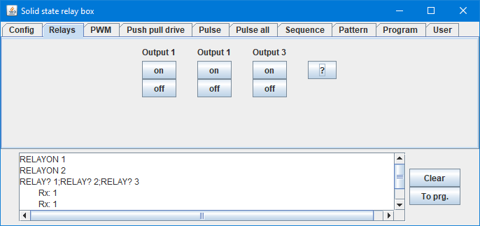
The "Relays" page is for turning each output on or off, the "?" will ask for the actual output status for the relay function.
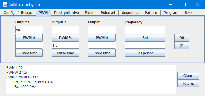
The PWM window switches the box to PWM, but first when PWM is requested. Here I asked for 50% on output 1 and 1.5ms high on output 2. This will mean 100% high because a cycle is 1ms or 1kHz (1000Hz). Using the fields below "Frequency" I could easily adjust this. The "?" returns the current PWM status.
The "Push pull drive", "Pulse", "Pulse all", "Sequence" and "Pattern" works the same way, see description of the commands above.
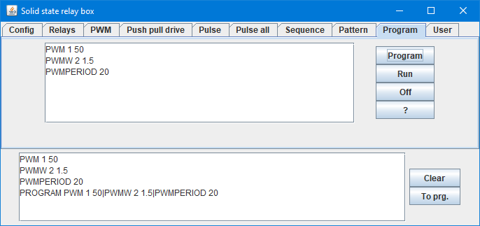
Program is different, it will store a couple of commands in the relay box. Here I have first given a couple of PWM commands, then pressed "To prg." that moved them to the program list (It is also possible to manually write commands here). Finally I pressed "Program" and they where sent as a program to the relay box.
Now they can be activated with the RUN command or with a press on the "RUN" button on the box.
The "To prg." command will remove any query command and any answers, before putting the text into the program list.
The "Program" key will replace ; with | and split the programming into one "PROGRAM" and as many "PA" as needed.
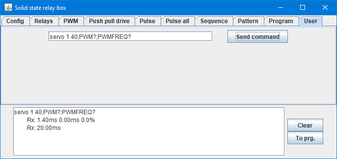
The "User" page is basically a terminal program, it is possible to write any command on the line and send to the box. Here I test the "SERVO" command and uses the query commands to see what it does.
Applications
It was designed for use with my automation, but with all the ideas I have stuffed into it, it has many other applications:
- Control from a computer with included program, any terminal program or own software.
- Protect the computer and tested equipment from ground loops or accidental shorts.
- Controlling on/off with up to 40V DC 10A on 3 independent and isolated channels.
- Two channels can be used together to switch a AC signal.
- Testing with PWM, trying different duty cycles and frequencies (Up to 100kHz).
- Testing with push pull drive, can be used for motors and transformers.
- Stroboscope, use PWM with fixed puls width and adjust the frequency (It only works above 1Hz or 60RPM).
- Emulating buck/boost circuits to see how a transformer behaves.
- Generating pulses from ten us to hours
- Turning stuff on in sequences with delays from ten us to hours.
- Generating on/off patterns with 100us to hours between updates, up to 64 steps.
- It is possible to store command sequences for the above and use offline.
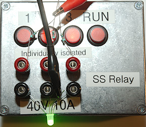
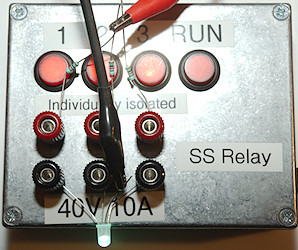
Playing with PWM on a multicolor led to find the right color, it could also have been a strip of multicolors leds.
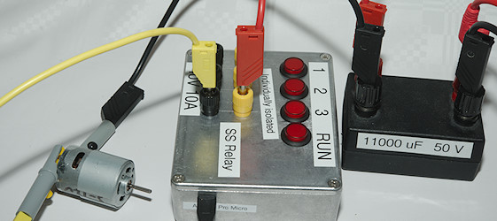
Finding a good PWM frequency for the motor.
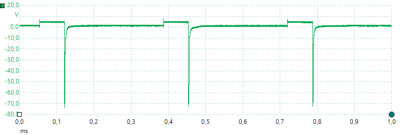
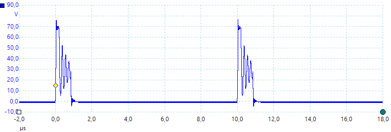
I did not bother with a diode. I am using a 5V supply, but get 70V kickback from the motor, the limit is probably because the MOSFET transistors break down at 70 volt
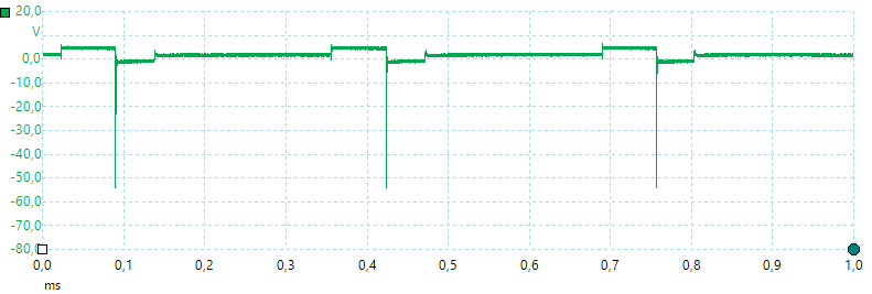
A diode across the motor takes a lot of energy out of the spike and limits the voltage.
Notes
This project is not finished yet, the actual software contains some extra functions for use with another box with logic level outputs I made later. This will be published in another article.
I do not expect many software updates, the Arduino is nearly full.
It was interesting to do a electronic design with circuit board again and with the current prices on circuit board it is probably not the last time I do it. It took some extra time to learn a new software package.
The design worked as expected and got considerable more advanced that was initially planned, but I like the final result.
The design files and source code is included with this project, this means anybody is welcome to duplicate it or improve it.
Arduino program
Gerber files
Java program and source
KiCad files
TestController, can log data from this device


